Rockdudes MegaDrum attempt (Build log)

Discussions related to MegaDrum Hardware

Re: Rockdudes MegaDrum attempt (Build log)

Postby rockdude » Tue Oct 06, 2009 8:52 pm

Ok, hope this helps. My explanation may seem blurry. But I can't make any pictures right now for you to go by :-(

Thank you very much for your explanation. With your explanation in words and a video I found afterwards (http://www.youtube.com/watch?v=TH9jL-L0K5Q) I finally understood how to do it.
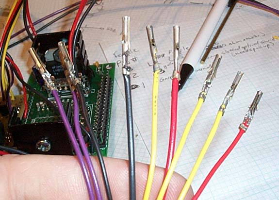
The result:
Image

Now IT IS VERY IMPORTANT that you pay attention to the WIRING. IT IS VERY EASY to mess it up and kill off your LCD. Triple check whether the connection is right.

Is this the correct way of thinking? I assume that the ribbon cable coming out from my lcd port on my Synthex board has 1 to 16 led out like in my picture, or am I wrong?
Image
rockdude
 
Posts: 276
Joined: Wed Sep 02, 2009 7:18 am

Re: Rockdudes MegaDrum attempt (Build log)

Postby jman 31 » Tue Oct 06, 2009 9:19 pm

You show the right way for the ribbon cable. I don't know about the LCD though. Look closely at the board (top and bottom). A lot of times they have a 1 at on end or the other that will clue you in.
jman 31
 
Posts: 536
Joined: Thu Jul 10, 2008 10:51 pm
Location: USA

Re: Rockdudes MegaDrum attempt (Build log)

Postby rockdude » Tue Oct 06, 2009 10:19 pm

You show the right way for the ribbon cable. I don't know about the LCD though. Look closely at the board (top and bottom). A lot of times they have a 1 at on end or the other that will clue you in.

Ok, great. Then I have total control in this aspect :)

Now to my next question....Is this the correct way of putting the following pieces together?
1. Peel the top of the cable.
2. Put the wire on the metal thingy and press together the metal so that the wire is stuck.
3. Press down into plastic positioned like in the picture.
Image

I'll turn my thread into a "MegaDrum for Dummies" when I have mine finished ;)
rockdude
 
Posts: 276
Joined: Wed Sep 02, 2009 7:18 am

Re: Rockdudes MegaDrum attempt (Build log)

Postby jman 31 » Tue Oct 06, 2009 10:27 pm

Yes almost. The lead goes in the other way though. You have it upside down. The little tab on the side of the pin that you can't see in the picture actually clips into the little square hole on the plastic part that you can see in the picture.

I usually solder mine instead of just squeezing them, but that is just personal preferance.
jman 31
 
Posts: 536
Joined: Thu Jul 10, 2008 10:51 pm
Location: USA

Re: Rockdudes MegaDrum attempt (Build log)

Postby jman 31 » Tue Oct 06, 2009 11:32 pm

It will click into place and won't come out when you have it in right.
jman 31
 
Posts: 536
Joined: Thu Jul 10, 2008 10:51 pm
Location: USA

Re: Rockdudes MegaDrum attempt (Build log)

Postby Firelord » Wed Oct 07, 2009 8:32 am

jman 31 wrote:I usually solder mine instead of just squeezing them

Same here. I wouldn't though if I had the special tool, but it's too expensive 8-)
Firelord
 
Posts: 666
Joined: Wed Jun 10, 2009 7:50 pm
Location: Estonia

Re: Rockdudes MegaDrum attempt (Build log)

Postby gui_999 » Wed Oct 07, 2009 5:30 pm

As you can see, there's 2 places where you can actually "crimp/bend" the pin..

Normally, I crimp the first one on the wire's plastic and the 2nd one on the wire's core (cooper/metal).. so that way the core touch the pin without soldering.. and crimping the 1st one on the plastic make it more solid


Image
gui_999
 
Posts: 20
Joined: Sat Apr 11, 2009 1:48 pm

Re: Rockdudes MegaDrum attempt (Build log)

Postby rockdude » Wed Oct 07, 2009 10:11 pm

Thanks guys for clarifying. I tried both solutions and they worked well :)
Image

I've also finished soldering the lcd:
Image
rockdude
 
Posts: 276
Joined: Wed Sep 02, 2009 7:18 am

Re: Rockdudes MegaDrum attempt (Build log)

Postby rockdude » Wed Oct 07, 2009 10:55 pm

I have some questions regarding connections between the main board, the 32 input board and the "button board".
I've made a photo montage to clarify a bit. It's silly questions but I need them answered to go on.

* "Usb" on main board connects to "Usb" on 32 input board?
* "Midi in out" on main board connects to "Midi in out" on 32 input board?
* "Keyboard" on main board connects to "keyboard" on "button board"? And if so, should I use pins shown above the "button board" in my photo montage or are they supposed to be somewhere else?
Image

If anyone have some photos of there connections between the main board, 32 input board and, 24 input board and button board I would love to see them :geek:
rockdude
 
Posts: 276
Joined: Wed Sep 02, 2009 7:18 am

Re: Rockdudes MegaDrum attempt (Build log)

Postby jman 31 » Wed Oct 07, 2009 11:34 pm

rockdude wrote:* "Usb" on main board connects to "Usb" on 32 input board?


Yes.

rockdude wrote:* "Midi in out" on main board connects to "Midi in out" on 32 input board?


Yes.

rockdude wrote:* "Keyboard" on main board connects to "keyboard" on "button board"? And if so, should I use pins shown above the "button board" in my photo montage or are they supposed to be somewhere else?


Yes, if a polarized header is not supplied.
jman 31
 
Posts: 536
Joined: Thu Jul 10, 2008 10:51 pm
Location: USA

PreviousNext

Return to MegaDrum Hardware

Who is online

Users browsing this forum: Majestic-12 [Bot] and 52 guests